The silicone 3D printer is a multi year project based on a 2018 research paper coming from Oregon State. In previous years, an Anet A8 filament 3D printer was modified and a custom extrusion head made using a Form 2 stereolithographic printer. Coming into this project the printer had only ever had a dry run, but was not in functional condition.
My first task was troubleshooting and attempting to sort out the spiderweb of wires controlling the printer; after adjusting the axis and leveling the bed properly, Xinghao and I attempted a dry run. Imminently it became evident that the two heating "wings", which help to increase the reaction rate of the curing silicone, were not very efficient, nor were the thermocouples reading correctly. After witnessing a small melt down of the left heating wing, it was decided that a more efficient heater and heater control was in order.
My first task was troubleshooting and attempting to sort out the spiderweb of wires controlling the printer; after adjusting the axis and leveling the bed properly, Xinghao and I attempted a dry run. Imminently it became evident that the two heating "wings", which help to increase the reaction rate of the curing silicone, were not very efficient, nor were the thermocouples reading correctly. After witnessing a small melt down of the left heating wing, it was decided that a more efficient heater and heater control was in order.
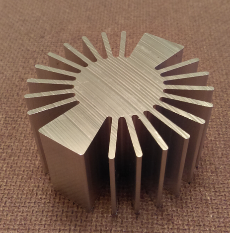
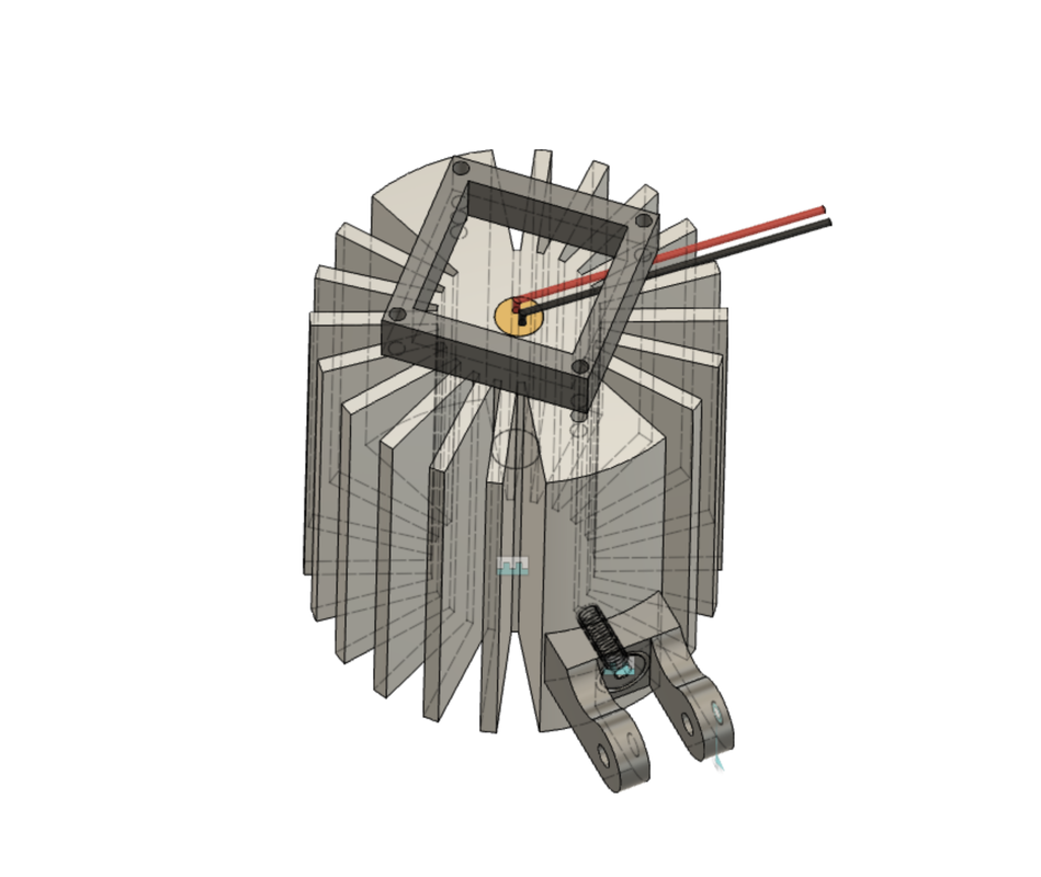
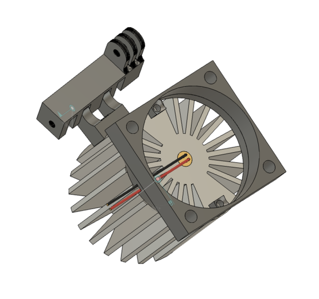
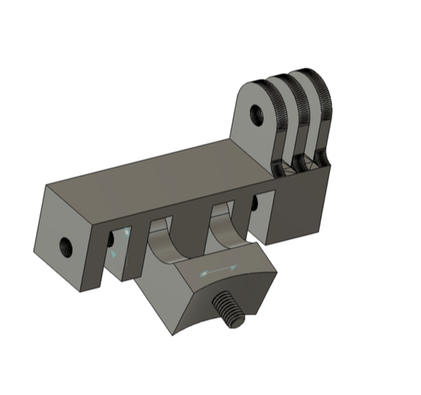
As with all college projects, minimum machining and re-fabrication (along with price) were the driving factors in my choice of materials; therefor the choice for heatsinks was clear: Ebay. Luckily, after a few pages of strange heatings, I came across this two inch round heatsink. The main problem with the previous "heatsink" was the lack of surface area, and location of the heating element. I aimed to address those issues by increasing the surface area close to the heating element, and warm up the heatsink more evenly, thus increasing the thermal transfer and the efficiency of the heat directed toward our build plate. Quickly drawing up the heatsink in CAD, I removed material for the heating element in the center, placed the fan blowing down the fins, and made a small mounting bracket to mount to the existing wing arms. As the wing arms are made of PLA, I plan to put a thin insulator in between the bracket and heatsink to prevent heat transfer (in this case I am not too worried about heat transfer through the bolt as the DLC coated screw should not be very thermally conductive). On the other hand, the heat transfer between heatsink and heating element are going to be aided by some sort of TIM (thermal interface material).
Later it was decided that the budged could be expanded to include larger fans as well. Sense this was the case, I opted for 50 mm fans, and a custom 3D printed shroud. ABS was the material chosen for the shroud as it has a much higher melting point than PLA, and smelling up my dorm room was well worth that trade off. A hole was also added under mount for the thermocouple, and new thermocouples should be on the order list if we can get enough funding.
Custom Extruder
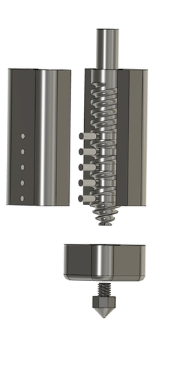
For this project I had hoped to design and make a extruder capable of taking in two part silicon, mix and extrude silicone with one chamber to relieve stress off the syringe pumps, and create a cleanable extruder that could be reused many times. In order to achieve this, I designed this part to be machinable out of several pieces of aluminum. For a small animated clip, download the MP4 file below, I would make it play in the browser, but I don't have any money to give Weebly after the mecanum wheel project that I have essentially been self funding.
| test_screw_v3.mp4 | |
| File Size: | 1453 kb |
| File Type: | mp4 |
The extruder is meant to take in the two part silicone at the top of the screw, where the helical groves will push the mix down to the tip where it will be extruded. The concentric groves perpendicular to the axis of rotation act as channels where the silicone can mix, similar to many industrial mixers from BUSS Neaders. the screw was designed to be machined using a 3 mm ball end mill on a milling machine with a fourth axis. Although I did get the CAM done, this part is still yet to be manufactured as I don't have the time at the moment, nor are the dimensions entirely set. obviously this part would still also need many features such as a few O-ring groves, mounting holes, and an attachment method to the stepper motor controlling extrusion.
