UCSB RPL Coaxial Swirl Injector
I joined UCSB's RPL team as the manufacturing lead on the injector team. My peroneal responsibilities included contacting and conversing with with third party manufacturing sources such as Xometry and Sculpteo as well as tweaking and optimizing the injector to make it more conducive to manufacturing. I am also solely responsible for the deign and manufacturing of a machinable coaxial swirl injector prototype which we plan to use if it found that additively manufacturing the injector is improbable.
| rpl_swirl_injector_design_packet_draft.pdf | |
| File Size: | 1271 kb |
| File Type: | |
|
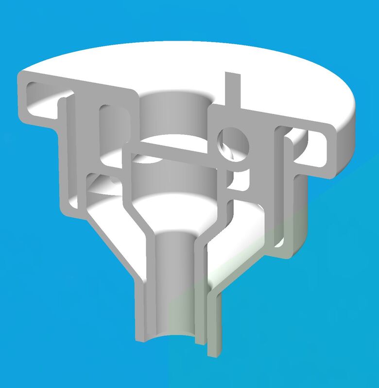
The original design was started before I joined the team, and was created with the intent to additively manufacture the injector. This posed many challenges as the injector not only has to undergo 300-400 PSI during the static fire, but will also encounter large swings in temperature, from well below freezing when the high pressure fuel and oxidizer expand and exit the injector, to high temperatures once the fuel has been ignited after exiting the injector.
Due to these parameters the logical manufacturing process was determined to be metal 3D printing. Originally DMLS was selected as the process of choice due to its high strength, material options, and high material density (99% base metal once complete). The only problem is DMLS is not only prohibitively expensive and produces a rough surface finish (10.5 micron ra) but also requires a complex support structure throughout the inside of the part (that would be impossible to remove) despite optimizing to minimize overhangs as well as reducing angled surfaces to a maximum of 45 degrees.
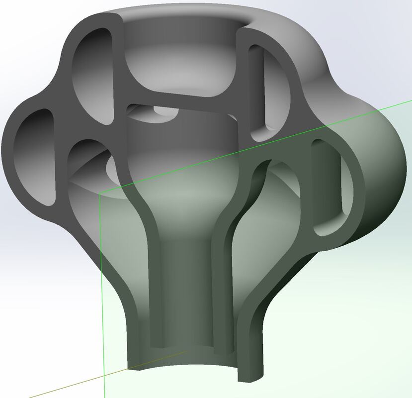
Due to the geometric constraints of DMLS it was determined that binder jetting may be a better manufacturing process for this specific injector. Binder jetting is not only about 1/6th the price, but is also able to produce almost limitless geometry due to the lack of necessary support structure. The process of binder jetting also produces a smoother surface finish (6 micron ra) but does lack the material density of DMLS with only 93%-97% of the part being metal, and the rest being air. This not only results in a slightly weaker part, but also introduces micropores and allows for a small amount of absorption of the fuel and oxidizer (not something you want with large swings in temperature)
|
Machined Prototype Coaxial Swirl Injector
|
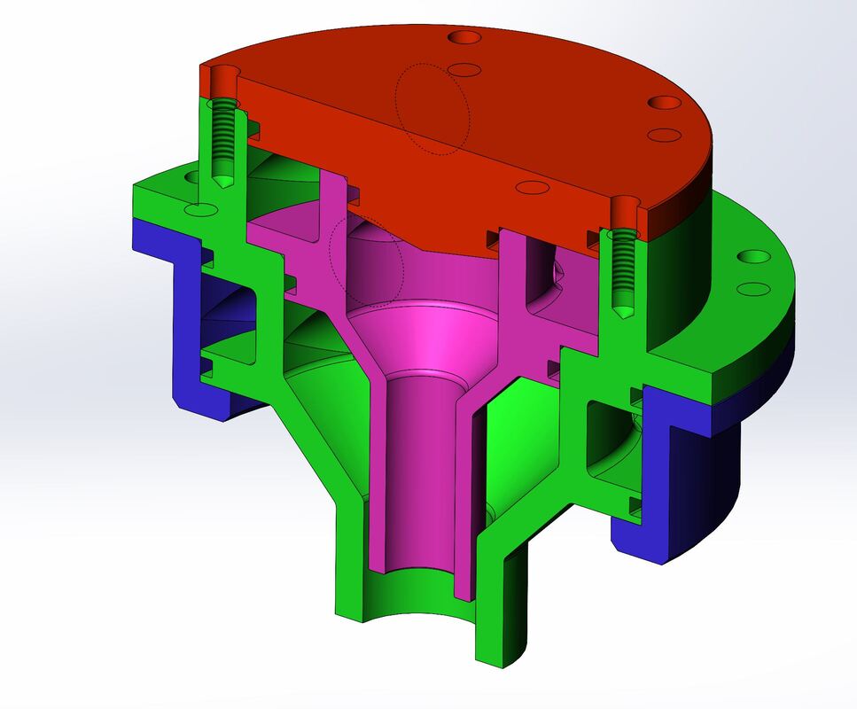
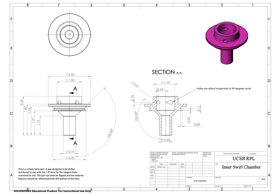
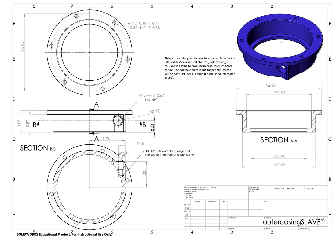
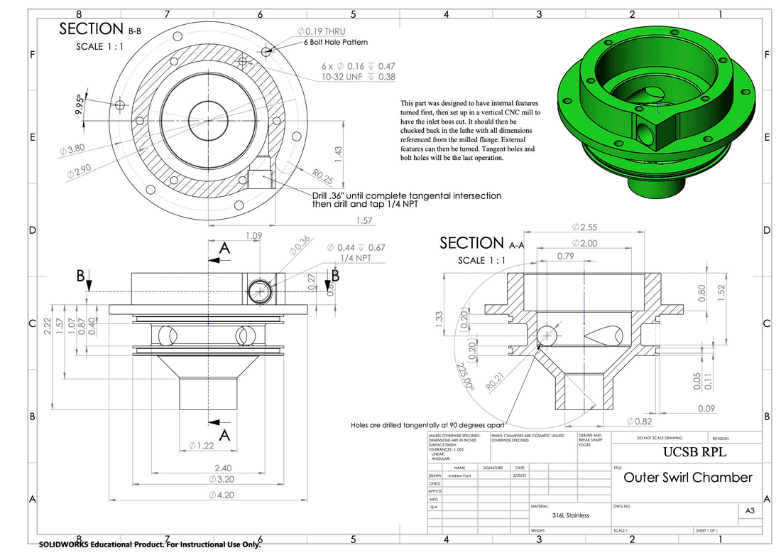
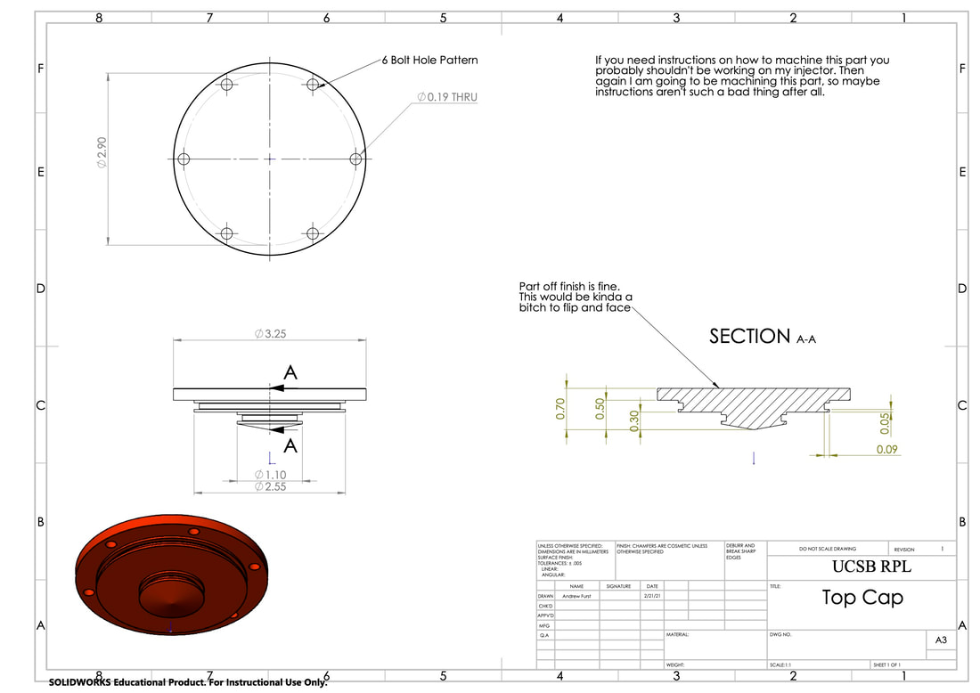
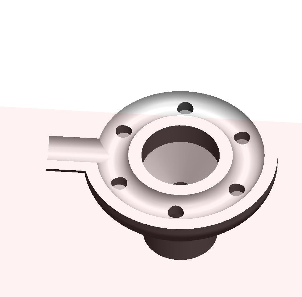
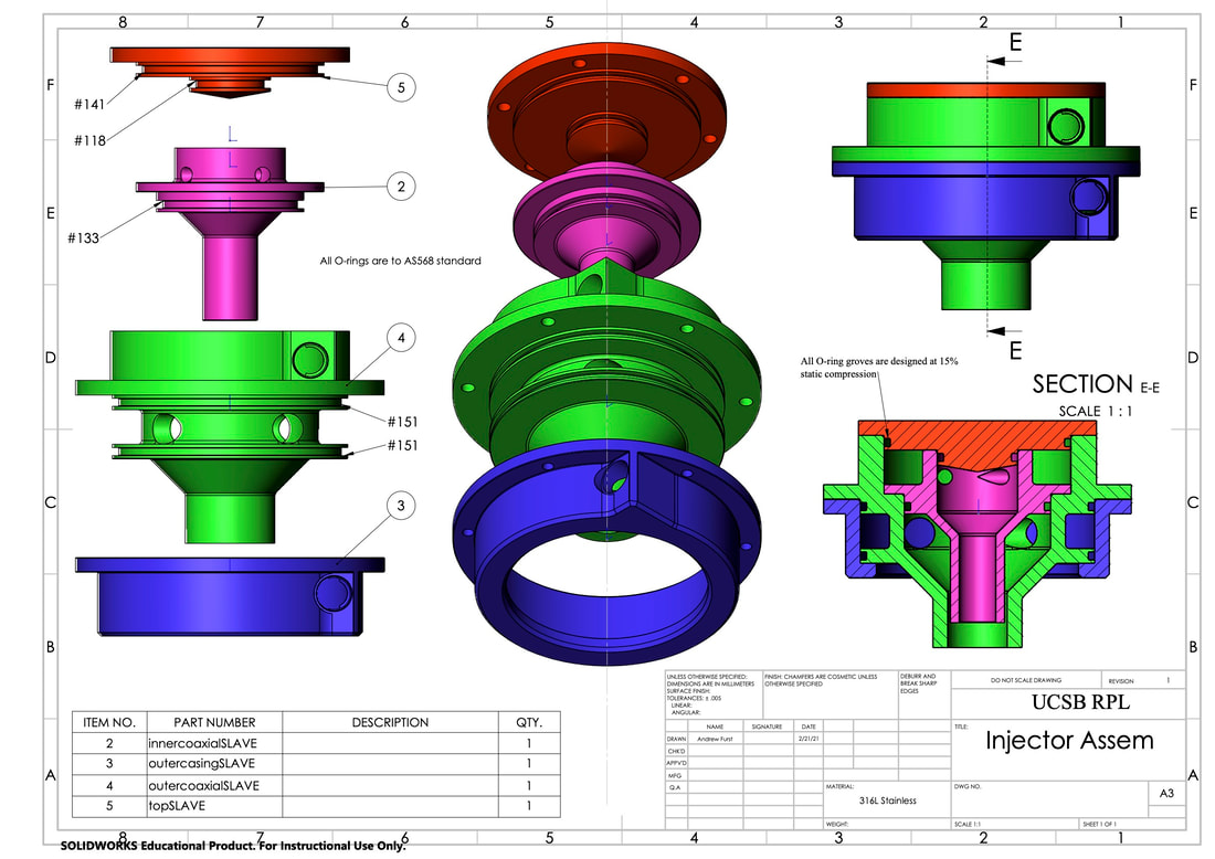
Due to my background being in the design and manufacturing of machined parts, I began work on a injector that was much more conducive to traditional styles of manufacturing. This injector was designed in four parts, and was sized so that I could personally manufacture the injector in my lab using a lathe and my beloved Haas. The injector relies on axial sealing O-rings to create seals, and although I would have greatly preferred to use sealing tapers instead (easier to manufacture, less parts to go wrong, nothing to rip) I settled on O-rings as the stack up of injector parts would result in a tolerance stack up, and a single surface that was ever .001 undersized could result in not enough pressure from the bolts to create sealing pressure on the all the tapers. The rapid changes in temperature and the varying thicknesses of material could also result in the tapers failing to seal at higher or lower temperatures due to the coefficient of expansion of our parts.
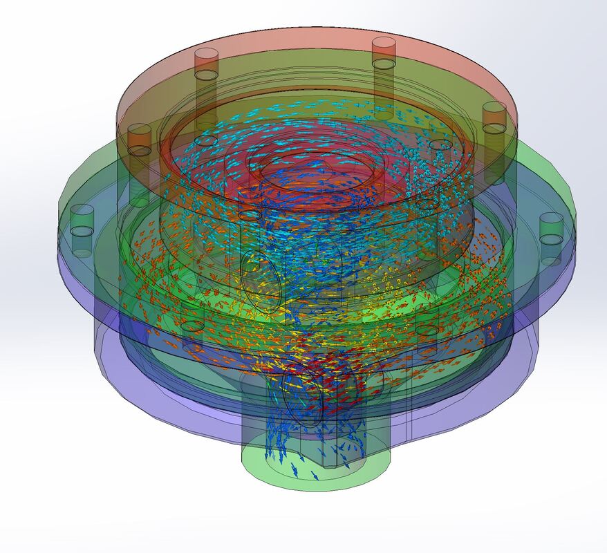
Although brazing the injector would have have provided a good long term seal that would be much less failure prone and easier to manufacture (less tolerances due to no o-ring groves) because of the fact that this was our first axial swirl injector, we wanted the ability to not only disassemble and check portions of the injector, but also adjust the geometric features of the injector if the ideal spray angle or pressure drop was not achieved. Being able to adjust one swirl at a time would save on cost and manufacturing time. In order to optimize the geometry of the coaxial swirl injector many tests were run using Ansys as well as Solidworks flow simulation (seen here). These tests were used to optimize the pressure drop over the injector and tune the vortex created in the inner and outer swirl chambers. Much time was spent optimizing the design to maximize said pressure drop without making the geometry impossible to manufacture. As a machinist first, I am lucky enough to have enough time working on the tools to create designs that not only function, but are also possible (and cheep) to manufacture.
|
With parts like this, thinking of error stack up and the order of machining features is critical in creating parts that are in spec. It was decided that all critical inner features would be turned first on a lathe, before moving each part to the mill for cross holes, bolt holes, and non round/not concentric features. After such operations the stock would be moved back to the lathe and placed in a 4 Jaw chuck which could be dialed in to minimal run out and the exterior features turned down to shape. As only interior features are incredibly critical and sealing features, it would be possible to turn all of the important features in a single set up to avoid introducing unnecessary error.
(yes I know these engineering drawings are not complete nor are they completely accurate. There are plenty of tolerances that can have much looser tolerance to make the parts more manufacturable, and there are several chamfers that need to have minimum dimension callouts to allow nesting parts to sit flush without having to undercut the corners)
Hybrid Injector Design
|
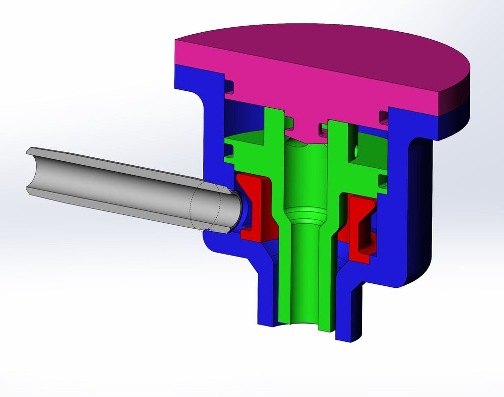
Due to the difficulty of calculating pressure drop and spray angle of the outer swirl, a design was proposed to design a hybrid injector with a swirling fuel injector surrounded by a (much easier to calculate) axial flow LOX injector. At first a design such as the one shown to the right was tried, but it was found that even with a gap of just .5 mm between the red insert and green swirl chamber resulted in uneven axial flow with a lower pressure drop on the side closer to the LOX inlet.
|
