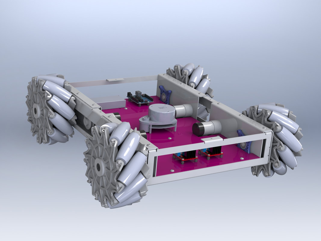
The mecanum wheel was one of the first projects where I led the design team; originally taking responsibility for designing only the mecanum wheel, it eventually became my job to design, fabricate, and assemble the mecanum wheel car as the rest of the team worked on electronics and sensor positioning. This was broken down into two main parts, the wheel, and the chassis, and each came with its own headaches and heartbreak.
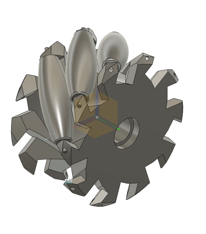
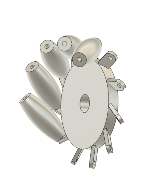
The wheel itself went through many different prototypes and design philosophies. Originally I started with a solid cylinder in CAD, and hollowed out areas for each of the rollers located within the wheel. Getting the correct angels required a decent amount of geometry (as well as a blood sacrifice) to get correct, and eventually I settled on positioning and creating the pattern for the rollers first, then using the rollers to set the sketch plane. This method guaranteed correct geometry without having two separate offset plains (one at 45 degrees for rollers, one to account for the curvature of the wheel), and allowed for dimensions to be changed after the wheel was designed without having to re-find all the angles manually.
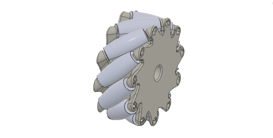
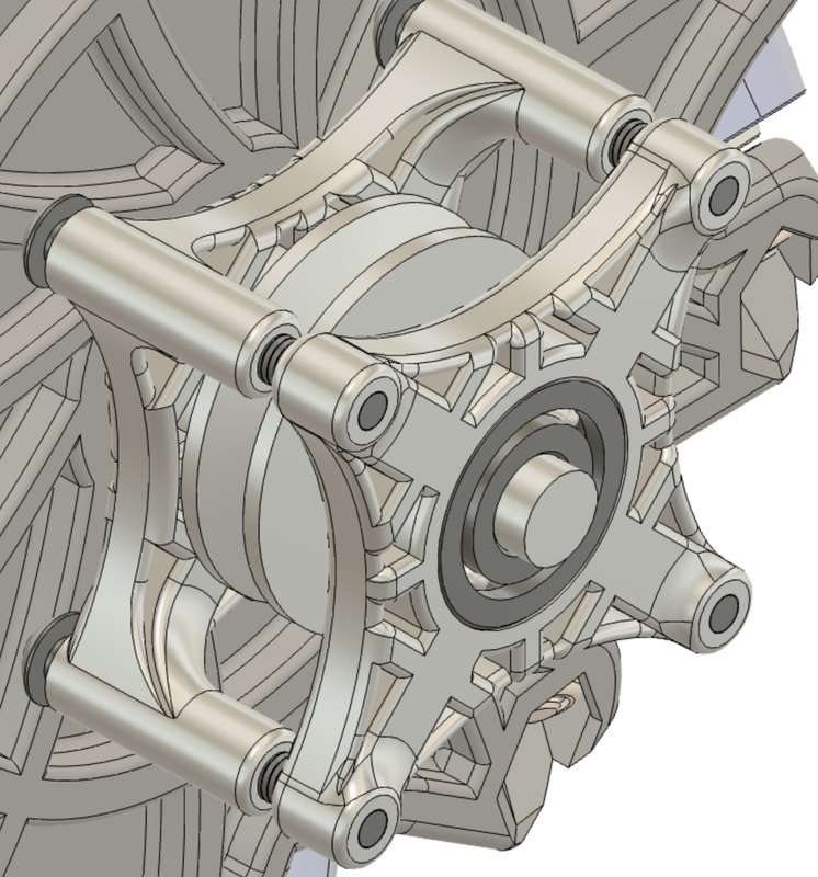
The wheel went through so many prototypes as it was originally meant to be machined from aluminum. Using the simulate function built into Fusion however, it became clear that a durable resin should be adequate. On account of this, the second draft of the wheel was made to be machinable with a rotary table on a mill, where as the third draft saw changes that would improve the structural ability of the wheel but also prevent it from being machined without a 5 axis mill. The second I knew I would not have to write the CAM for the mecanum wheel, I increased the amount of supporting material, and removed all of the stress inducing angles. The hex patterns seen on the right side of this wheel are sized to retain the nut on one end, and the head of the roller bolt on the other.
If there is one thing that I learned doing this project, it's that sheet metal is a royal pain in the butt. Due to the size and strength requirements of the chassis, 2mm thick aluminum was used in every sheet metal component. Originally the plan was to bend, then weld the chassis together, but soon it became evident that fasteners were more practical due to the complexity of the parts. Plenty of time was spent thinking of each bend, and bend order to make sure it could be fabricated with the metal break available; in fact, originally the entire chassis was to be built out of a single piece of aluminum, and I was just going to manhandle the hard to reach bends as this is just a one off project. I did however settle on separating it into many sheet metal components to reduce complexity/cost and increase our available margin for error when fabricating.
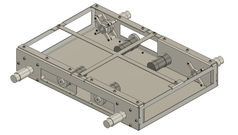
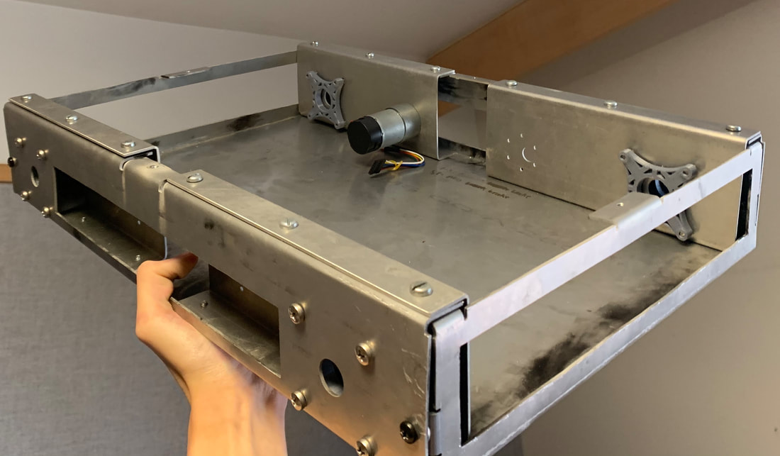
Here the frame is visible with one of the clamshells removed in order to see the axel support plates, spacers, and pulleys. The clamshells serve double purpose to both act as a motor mount, and supply some onboard structural support for the bearings the axel rides on. The original plan was to connect the motor directly to the frame and axel, but this design allowed for improved rigidity, balance and a more conducive frame layout for the electronics to come. From this angle the many screws and tabs responsible for holding the frame together are visible.
|
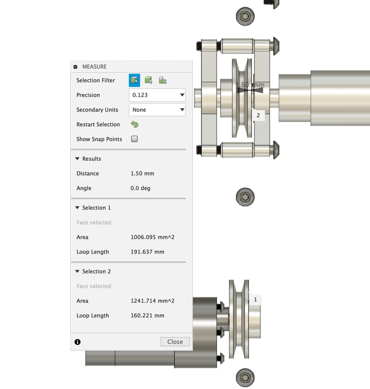
Unfortunately upon the motor arriving we noticed that the actual shaft length and collar length were longer than the provided specs they had provided. After adjusting the dimensions in CAD, the offset was found to be (at worst) 2 mm offset over 115 mm (from center to center). This yields a belt angle of .999 degrees, which is twice allowable angle of a traditional V-belt, but sense we are planning on using round belts at low torque and rpm, I was not too concerned.
|
On To Fabrication!
I decided that 6061 aluminum would be great for the construction of the chassis, with its rigid and weldable properties being of benefit to the long, flat, and load bearing sides of the frame. A five and a three series of aluminum where also available (we will come back to this later), but if I was going to make this chassis, I wasn't going to settle for no 5052.
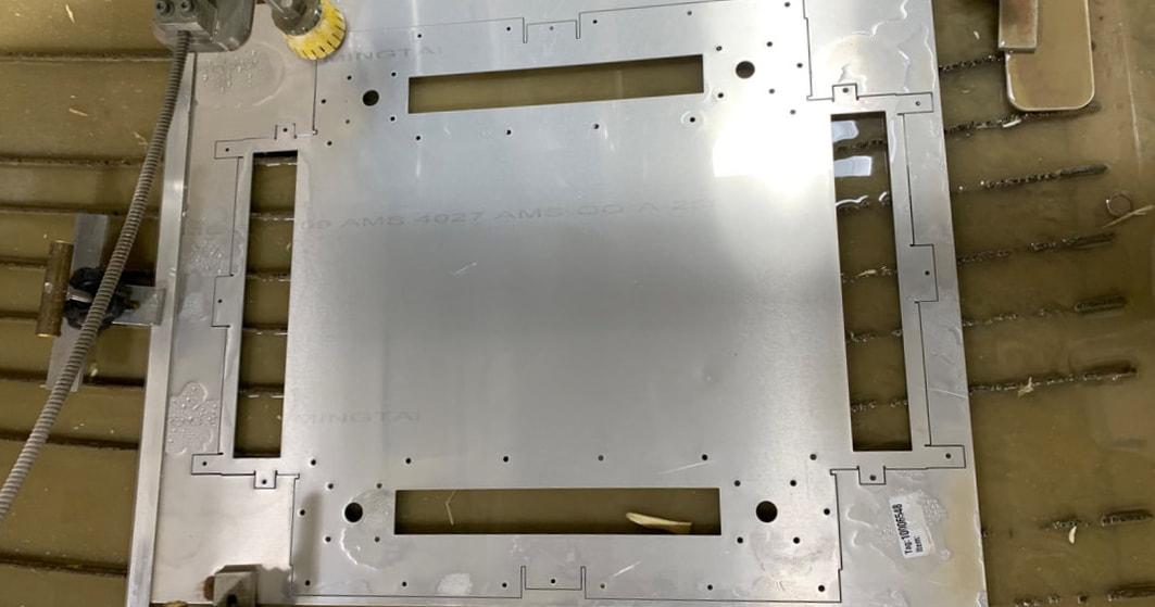
The first step was getting the aluminum sheet water jet cut, as the many small, precisely placed holes made the colder temperature of water jet cutting more appealing than melting our aluminum with a laser or plasma cutter. The DXF from the flat pattern of the frame and clamshells was edited than exported to the water jet cutter, which used a fairly basic 2D CAM software similar to Trotec's JobControl to create the G-code.
The first step was getting the aluminum sheet water jet cut, as the many small, precisely placed holes made the colder temperature of water jet cutting more appealing than melting our aluminum with a laser or plasma cutter. The DXF from the flat pattern of the frame and clamshells was edited than exported to the water jet cutter, which used a fairly basic 2D CAM software similar to Trotec's JobControl to create the G-code.
With our newly water jet chassis, it was time to begin the bending process. Taking a test piece to the pan brake, the aluminum cracked well before the necessary 90 degree bend. I did anticipate this however, and, had a back up plan. What I did not manage to anticipate however, was our aluminum frame warping into a Pringle during annealing.
|
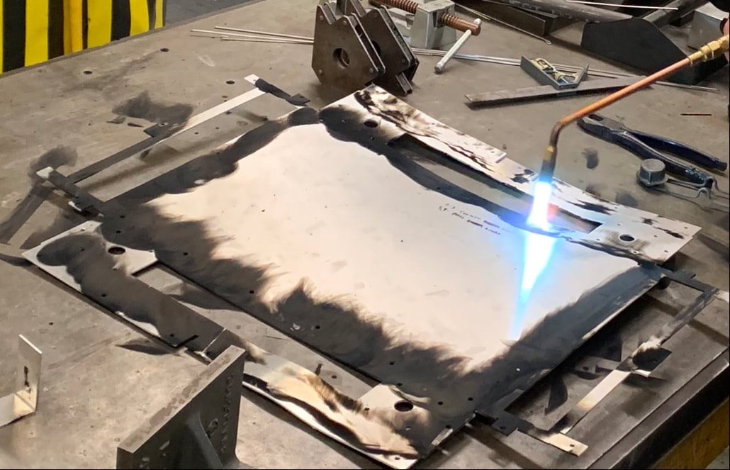
In order to achieve the necessary bends, the T6 6061 aluminum needed to be annealed first. The chassis was first coated in soot from an oxy acetylene torch burning only acetylene, thus producing an unnecessary amount of carbon which coats everything, and even rains from the air. Interesting fact, this same process can be used to make carbon nanotubes, with excess carbon being deposited in an ordered manner in an evacuated chamber. This carbon vaporizes off the surface at around five-six hundred degrees Celsius (Celsius because I'm not a heathen), which is conveniently around the same time the aluminum becomes annealed.
|
After several attempts to light the torch (its been a while sense I last used an oxy fuel torch) I figured the hardest part was over, just heat till soot burns off, right? WRONG, the second real heat was applied, the thinner ends of the chassis began to warp as the metal expanded. Having not considered this, I handed off the torch to Andy, my boss and shop manager, who claimed to have never seen this sort of warping on 6061, even going as far to double check our alloy. With no other choice I was forced to forge onward, literally. After finishing slowly heating the chassis and possibly defeating the the temper on the entire chassis instead of just along the bends as I had hoped, the clamshells were placed in a heat treat oven and tempered back properly at 550 C°. In a surprise to nobody, these properly heat treated parts turned out perfect; it is truly a shame that the heat treat oven was not large enough to temper our large 6061 T6 sheet into overpriced 6061 T-nothin (told you we'd come back to this). As it turns out, Roger Green, who helpfully allowed me to run his water jet cutter, had suggested a three or five series aluminum from the time I ran the project by him; thus earning me the most well deserved "I told you so" of all time.
|
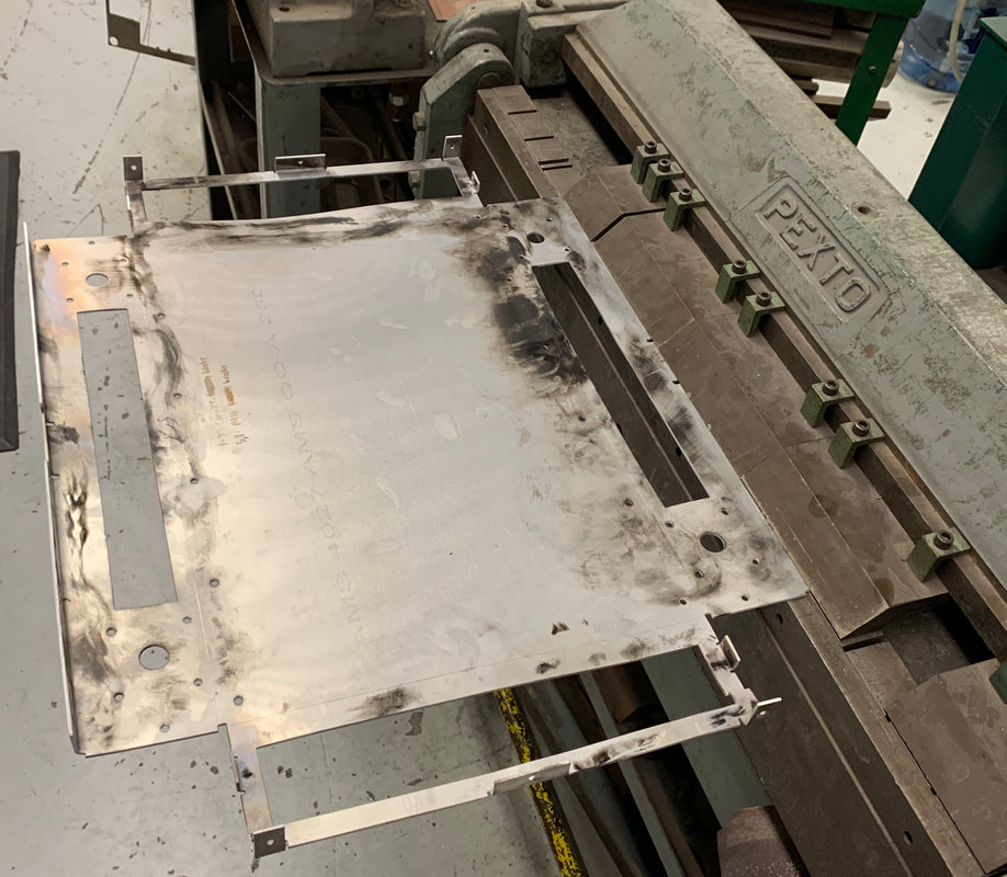
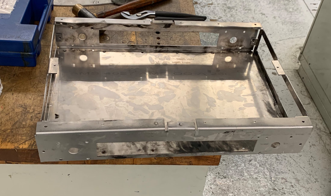
With the heat treat complete, it was time to begin bending the potato chip, which thankfully began to flatten as it was bend. My careful planing and ordering of bends however, were thrown off as I discovered the full length bend which creates the two sides was too much for our press break. Thus I was forced to do the two remaining side bends (which in this picture are yet to be bet) using the pan break, causing the bends to be slightly off center to avoid destroying the overhanging tabs (bent and lighted up on the press in this picture)
|
Obviously at this point the chassis required quite a bit of fine tuning, and even still to this day is not quite perfect (much to my displeasure). The clamshells were later bent, and installed with more screws than I care to count. This frame was my first experience working with sheetmetal, and I can safely say if I were to design this again, I would simply rivet extruded aluminum square tube together on top of a metal base, which would create both the inner and outer mounting points for the wheel support bearings and cut down on the cost of stainless hardware!
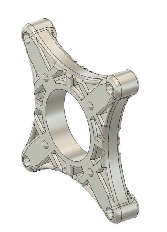
In the above picture, both the inner and outer bearing supports have been installed on the clamshells, and are held in place with long through bolts. This presented the next problem, how to deal with the slight misalignment of the clamshells in relation to the sidewalls of the main frame. This slight error came during bending, as one slightly misaligned bend due to a weak ass press brake can cause error along the entire rest of the chassis. To combat this, I designed the bearing supports to align themselves based on the four screws rather than the chassis itself. In essence, I floated the bearing supports on the bolts by using small contact patches on the bearing support plates where they contacted the frame.
