FormLabs Research Printer Modifications
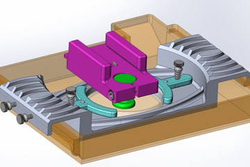
After receiving a very expensive and very broken CellLink Lumen X DLP printer, our researchers were looking for a easy (and working) method to test small amounts of custom photosensitive resin. Previously the MiiCraft printer had been used for custom resins however it proved unreliable and difficult to clean. A decision was made to use one of the FormLabs printers to test 405nm UV curing, which although having a slightly lower resolution then the MiiCraft, proved to be much more reliable over time.
There were three design goals set for this project:
- Use petri dishes as the resin tank to allow researchers to print using only a few mL of custom resin
- Make the custom resin build tank/platform easily interchangeable/replaceable with other non modified tanks
- Make a design that requires very little set up or instructions as researchers don't like reading my SOP's so why would they want to read my instructions
|
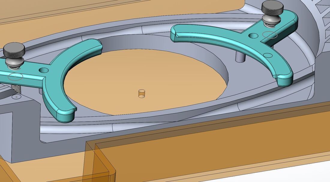
Arms are sitting on top of dowel pins ready for a petri dish to be loaded
|
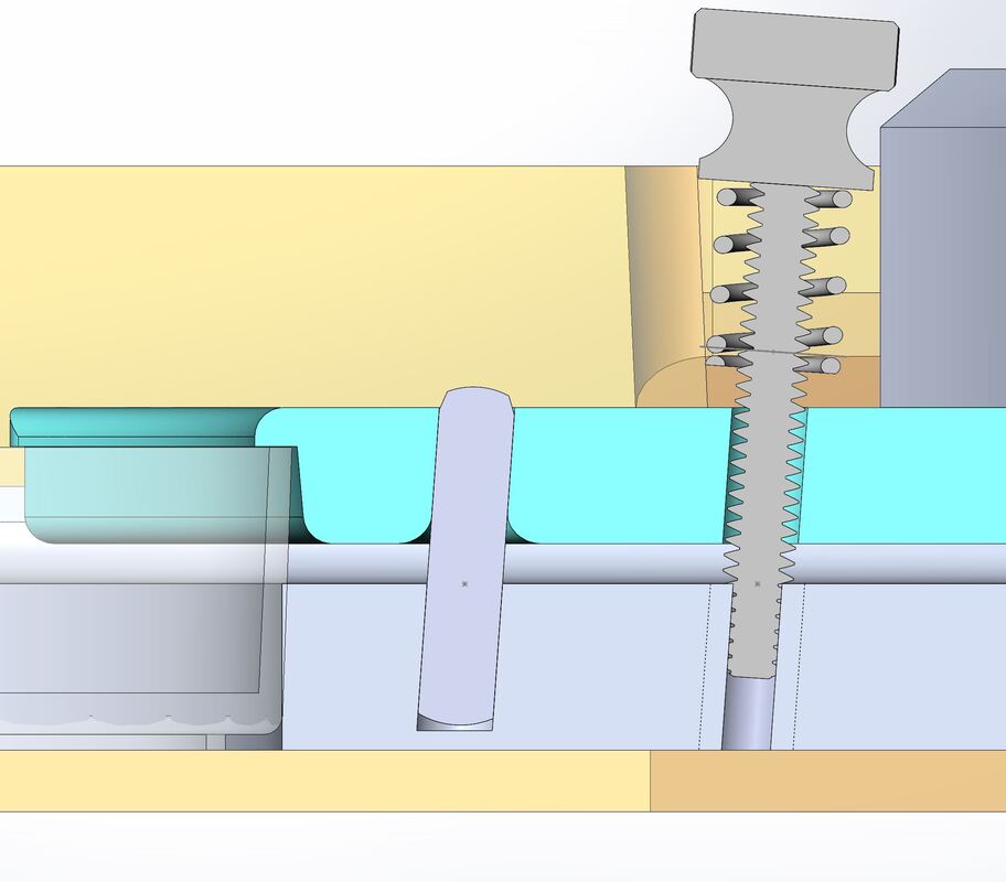
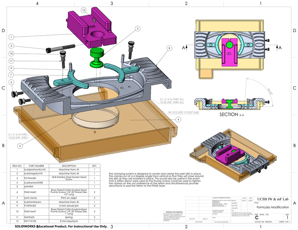
The petri dish clamping mechanism was heavily inspired by the Lumen X because, well, its a good design. I did make some slight modifications to design however that I think make it a small bit better. The dowel pin and thumb screw with spring are both tipped at 4 degrees from vertical so that when they lower they also begin to clamp onto the petri dish and center it within the build tank. When researches wish to remove the petri dish they can simply pull up on the clamps, raising them above the dowel and rotating them slightly so that they rest on top of the dowel head.
This design would also be useful if the researchers wished to print directly on the PDMS build platform layer without the petri dish. Instead the clamps would hold down and center a Teflon donut, sealing it against the PDMS layer. Although different clamps would have to be made, the 4 degree posts could still be used to guide the clamps in down and towards the build tank, centering and sealing it against the PDMS. |
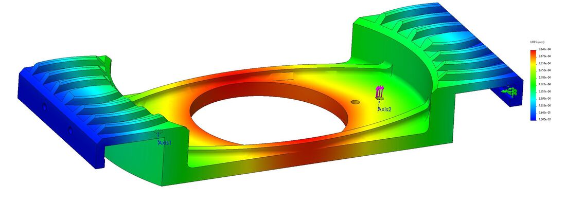
A Solidworks stress simulation was done and found that under the clamping load of the springs the very center should experience no more than a thousandth of deflection. Without the stiffening ribs there was significantly (about 3x) more deflection at the center of the beam. The fillets and chamfers are done more because if I'm going to be doing all the work to write the CAM and machine the part on all 6 sides, I may as well make it look pretty in the process. Wild mix of filets and chamfers were used, not because that's necessarily the right thing to do, but because I don't think my manager would approve an order for a bunch of custom radius cutters, and because even I'm not crazy enough to 3D machine everything (even though those toolpaths are sexy as hell).
