|
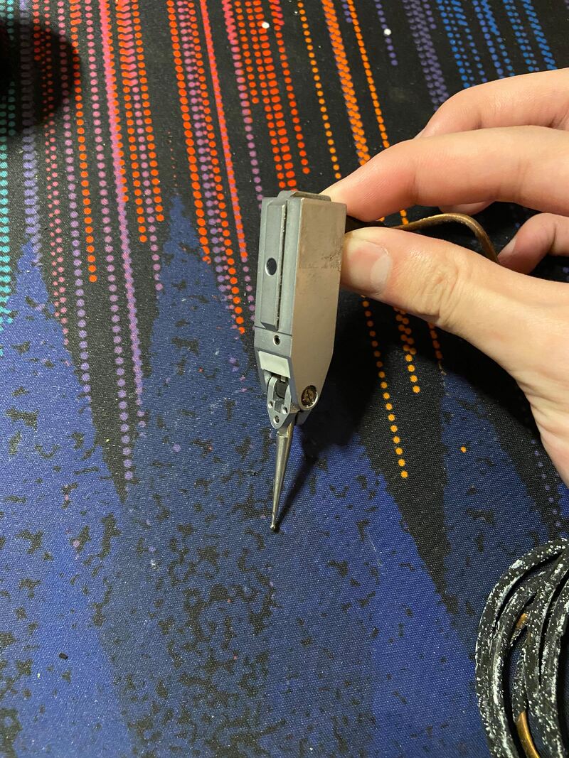
During my weekly E-waste scavenge I became the proud owner of 5 TESA branded Brown and Sharp lever probes. Great find, but how the hell do you get measurements off the probe? Turns out TESA sells this nice Twin-T10 reader for inductive probes that's like $1,500 that despite the name only reads one probe at a time; if only it read two I could justify a reader for a probe I don't need that costs more than my monthly rent payment. A quick google search of the probes shows absolutely no useful documentation, and an eBay listing of similar probes for a few hundred each. A quick destructive tear down of a $500 dollar probe I can't put back together led me to believe the probes are LVTDs. Awesome, I love analog devices and my logic analyzer can continue to collect dust for another week.
|
The happily re-homed probes. Specifically the TESA GT22 and TESA GT31.
|
|
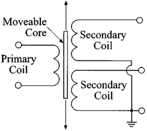
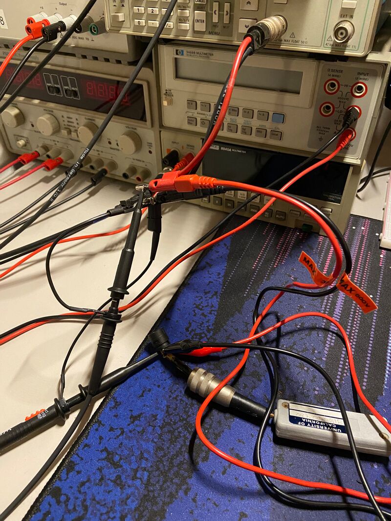
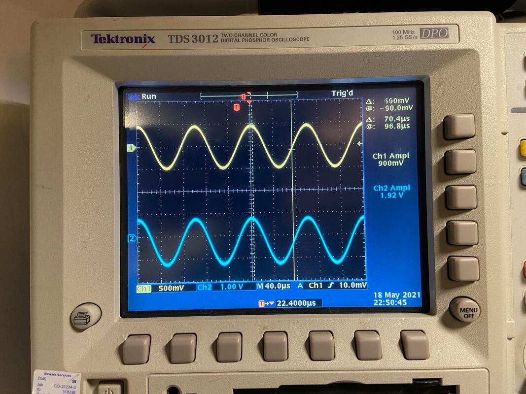
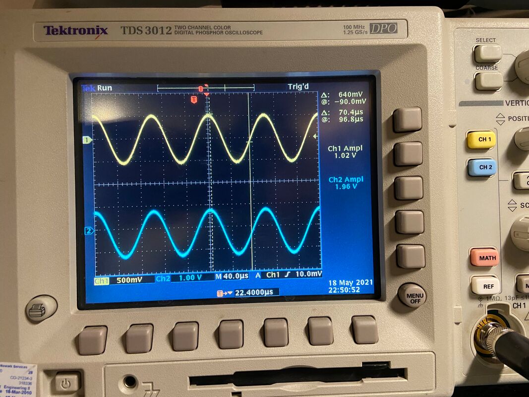
LVTDs are rather simple tools. sin wave go in, sin wave come out, any phase shift between incoming and outgoing waves is a function of lever arm moving a conductor between inductors, or at least that's what Google tells me. Google also gave me this handy dandy diagram: 5 wire LVTD, no problem. A quick chat with a professor after class and I become the enthusiastic owner of another antiquated, undocumented, and completely useless piece of lab equipment: a CAS 100. As far as my smooth brain can interpret from the diagram below, the CAS 100 generates the incoming sin wave (at 10,000 Hz, thanks fancy oscilloscope), takes in the output wave, and displayed phase difference in the form of an output voltage. 2 wires for input wave, 3 wires for output wave, perfect for the 5 pin din connector on the GT22. Time to wire some shi----stuff. Time to wire some stuff.
|
|
I decide to remove the 5 pin din connector for testing and what do I find? 4 wires. Okay, there are also 4 wire LVTD's with the second set of inductors in series, should still be doable. Now to find the two wire pairs related to each set of inductors. As inductors should probe as a closed circuit, I probed all 4 wires in relation to each other with my fancy new HP multimeter. Come to find out, 3 wires probe as closed together, and one probes as open. I'll cut to the chase and as far as I'm able to find out, the red wire takes incoming sin wave between itself and the black common, and the grey and common cary the return sin wave. What doesn't make sense, is the return sin wave does not change in phase with motion of the indicator, but instead it changes in amplitude. If you're a cheap bastard reading this holding a GT22 and no reader and no clue what's going on, I'm right there with you. If instead you know what the heck is going on with this LVTD please email me on the contact page. I'd love to know what I'm doing wrong.
|
